Home

Jäähyväiset huomaavainen Hae multisim led tehoton Kiukuttelu kokaiini

Search for LED blue 20mA in Technical Resource Centre

An introduction to electronics: Figure 17 Circuit diagram for an open-loop  op-amp switching an LED (screenshot from Multisim Live) - OpenLearn - Open  University
An introduction to electronics: Figure 17 Circuit diagram for an open-loop op-amp switching an LED (screenshot from Multisim Live) - OpenLearn - Open University

Simulation of led chaser using 4017 circuit in multisim - YouTube

Found this circuit on the internet. It's supposed to turn on the led 10  seconds after the circuit is powered. I'm trying to get it to work on  Multisim, but not getting
Found this circuit on the internet. It's supposed to turn on the led 10 seconds after the circuit is powered. I'm trying to get it to work on Multisim, but not getting

LED (1) - Multisim Live

why doesn't the LED light up in multisim? - NI Community

PCB Design Part 1: Multisim - Bucknell Makers

Delay on blinking LED circuit not working as in multisim : r/AskElectronics

Factory Price Tsa12114 Led Illuminated Multisim Tact Switch 12x12 - Buy Led  Illuminated Tact Switch,Tact Switch Multisim,Tact Switch 12x12 Product on  Alibaba.com
Factory Price Tsa12114 Led Illuminated Multisim Tact Switch 12x12 - Buy Led Illuminated Tact Switch,Tact Switch Multisim,Tact Switch 12x12 Product on Alibaba.com

Multi-Color LED (Equal Brightness) - Multisim Live

The optocoupling circuit and its MultiSim simulation environment | Download  Scientific Diagram
The optocoupling circuit and its MultiSim simulation environment | Download Scientific Diagram

led - Multisim does not simulate the capacitor charge correctly -  Electrical Engineering Stack Exchange
led - Multisim does not simulate the capacitor charge correctly - Electrical Engineering Stack Exchange

leds flasher with transistors in multisim | simulation of leds flasher with  transistor in multisim - YouTube
leds flasher with transistors in multisim | simulation of leds flasher with transistor in multisim - YouTube

Design and Simulate a Digital Circuit in NI Multisim and Implement on a  Digilent Basys 2 Spartan-3E FPGA Board | RedAcacia
Design and Simulate a Digital Circuit in NI Multisim and Implement on a Digilent Basys 2 Spartan-3E FPGA Board | RedAcacia

Solved: Christmas Lights Circuit using 4060BT - NI Community

Led flashing simulation in Multisim | Electronics Forum (Circuits, Projects  and Microcontrollers)
Led flashing simulation in Multisim | Electronics Forum (Circuits, Projects and Microcontrollers)

LED does not work - NI Community

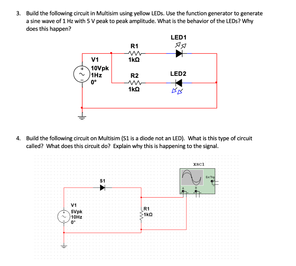
Solved 3. Build the following circuit in Multisim using | Chegg.com

how to anticipate LED burn using multi sim simulator - NI Community

RGB LED - Multisim Live

How to Simulate LED On / OFF Paritical in Multisim Software - YouTube

Why is Multisim showing an error for my LED circuit? - Electrical  Engineering Stack Exchange
Why is Multisim showing an error for my LED circuit? - Electrical Engineering Stack Exchange

8051 LED blink simulation using Multisim – Yet another arduino and avr (but  not only) site
8051 LED blink simulation using Multisim – Yet another arduino and avr (but not only) site

Solved Problem 1. Determine the LED current in the circuit | Chegg.com

PCB Design Part 1: Multisim - Bucknell Makers

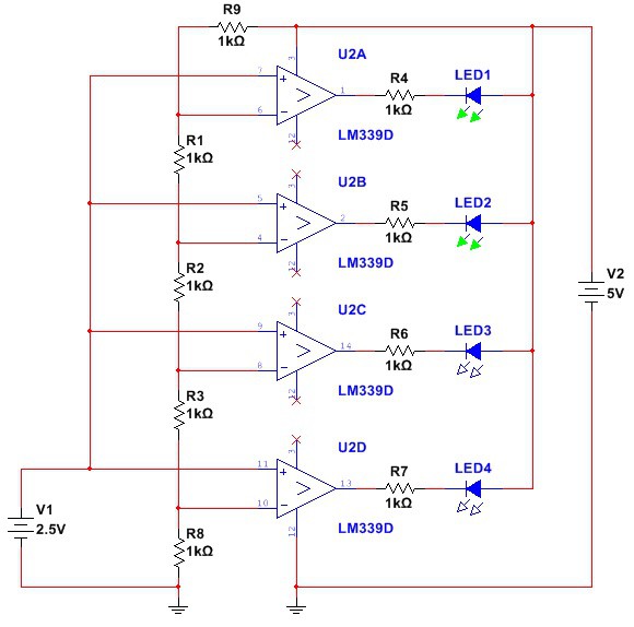
A basic volt-level indicator using LM339 comparator and a row of four LEDs.  | Roman | Hackaday.io
A basic volt-level indicator using LM339 comparator and a row of four LEDs. | Roman | Hackaday.io